
Navigation System: Radio Command
While waiting for the integration of ROS (Robot Operating System) and the Rover management software on the control station server, we used the Flysky FS-i6 remote control and its Flysky FS-iA6 receiver to set up the code logic and conduct various tests (e.g., motor and servo motor tests). Later, after integrating ROS, the Flysky FS-i6 remote control and its Flysky FS-iA6 receiver will be replaced by an Xbox controller. This controller will be connected to the management software for remote control of the Rover via Wi-Fi.
How the Flysky FS-I6 Works? 🎮
| Channel | Usages |
|---|---|
| Channel 1 – Right Joystick, Left/Right | Controls four servo motors connected to the Rover’s front and rear wheels, allowing turning movements |
| Channel 2 – Right Joystick, Up/Down | Controls six motors connected to the Rover’s wheels, enabling forward and backward movement |
| Channel 3 – Left Joystick, Up/Down | Controls the rotation (clockwise/counterclockwise) of the stepper motor connected to the Rover’s neck for a 360° camera rotation |
| Channel 4 – Left Joystick, Left/Right | Controls a servo motor connected to the Rover camera block, allowing tilt movements (up-down) |
How Does the Rover Handle Turns? 🔄
Ackermann Steering Geometry ⚙️
The four steerable wheels (two front and two rear) each have their own steering mechanisms, equipped with REV-41-1097 servo motors from REV ROBOTICS. To enhance the rover’s maneuverability during turns, we implemented Ackermann steering geometry on the steerable wheels. Widely used in automotive steering systems, Ackermann steering geometry ensures that during a turn, the inner wheels have a larger steering angle than the outer wheels, reducing tire wear and optimizing performance.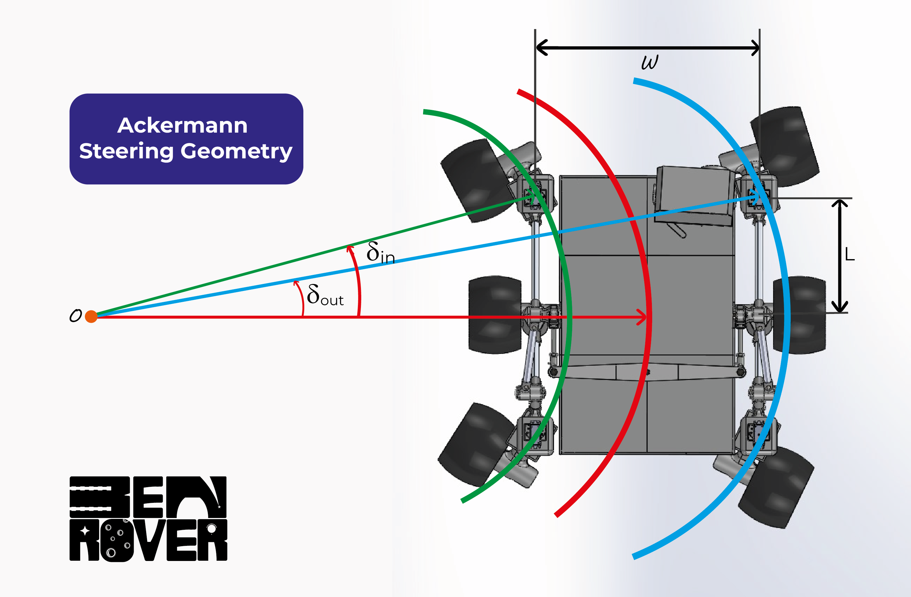 Ackermann steering geometry ensures that during a turn, the outer wheels trace a larger arc than the inner wheels, as seen in the diagram above.
Mathematical Principle Behind Ackermann Steering Geometry 📐
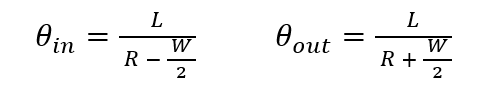
- L: Wheelbase
- R: Turning radius
- W: Track width
Navigation System: Sensors
A Raspberry Pi 4 model B controls the sensors (MPU6050, USB Camera). The MPU6050 is connected via I2C and provides temperature, gyroscope, and accelerometer data. Additionally, data from the power supply (e.g., temperature, battery level) is sent over I2C to an online database. The vision system is handled by a USB camera connected to the Raspberry Pi. Themotion package, installed on the Raspberry Pi, is used to stream video over Wi-Fi.
The control station is connected to the same network as the Raspberry Pi, allowing access to the continuous video feed via a web browser at the Raspberry Pi’s IP address and port (e.g., 10.10.10.5:9000). After testing, we obtained images with an appropriate resolution.