 Those servo motors, as specified by the constructor in the electrical specifications’ table on the following page, Smart Robot Servo Specifications, have a stall current of 2 A at 6V. Each servo can draw 2 A current at maximum load from the power source and requires a PWM pulse range from 500 µs to 2500 µs from a microcontroller for control.
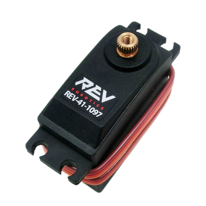
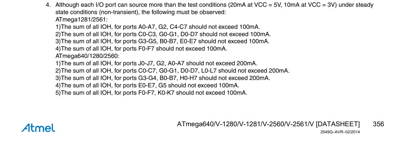 As per the ATmega2560 datasheet, the Arduino Mega board can only source 20 mA of current on its pins, which is enough to drive one servo. However, since we are using four servos, and due to electrical constraints of the ATmega2560 itself, we need to amplify the current.
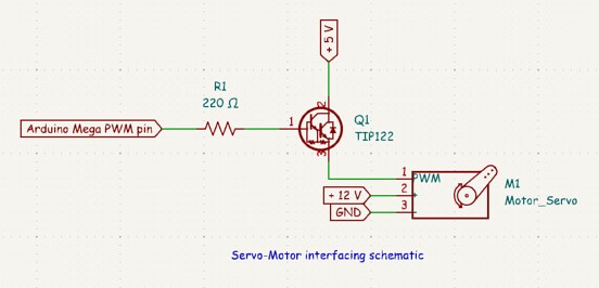
To ensure that all servo motors work correctly and simultaneously on the Arduino Mega board, we decided to design an interfacing circuit between the servo motor signal pins and the Arduino Mega’s PWM pins. This circuit uses TIP122 transistors to amplify the 20 mA current provided by the Arduino Mega.
As per the ATmega2560 datasheet, the Arduino Mega board can only source 20 mA of current on its pins, which is enough to drive one servo. However, since we are using four servos, and due to electrical constraints of the ATmega2560 itself, we need to amplify the current.
To ensure that all servo motors work correctly and simultaneously on the Arduino Mega board, we decided to design an interfacing circuit between the servo motor signal pins and the Arduino Mega’s PWM pins. This circuit uses TIP122 transistors to amplify the 20 mA current provided by the Arduino Mega.
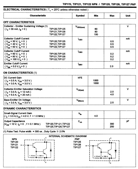 The TIP122 is a Darlington transistor capable of amplifying by 1000 the current received at its base, with a collector current of 0.5 A at 3 V, as indicated in the datasheet. Note that its current limit is 5 A. Additionally, the TIP122 can switch signals at a maximum frequency of 1 MHz, which is sufficient for transmitting and amplifying the PWM pulses from the Arduino Mega board to the servo motors.
Here is the schematic of the interfacing circuit used on each signal pin:
The TIP122 is a Darlington transistor capable of amplifying by 1000 the current received at its base, with a collector current of 0.5 A at 3 V, as indicated in the datasheet. Note that its current limit is 5 A. Additionally, the TIP122 can switch signals at a maximum frequency of 1 MHz, which is sufficient for transmitting and amplifying the PWM pulses from the Arduino Mega board to the servo motors.
Here is the schematic of the interfacing circuit used on each signal pin: